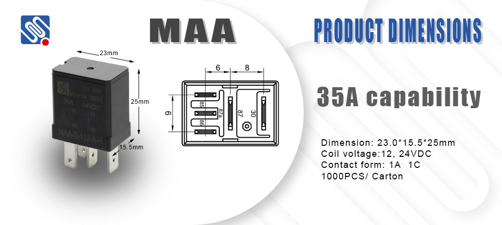
Here are some common components and symbols used in a relay electrical diagram:

Relay Coil (Magnetic Coil): This is represented by a rectangle or a circle with two terminals, and it is the part that gets energized by the control signal. When energized, it creates a magnetic field that operates the relay’s switch mechanism. Contacts: Relays have a set of contacts that open or close depending on the state of the coil. These are usually represented as switches in the diagram. NO (Normally Open): The contacts are open when the relay coil is de-energized and close when energized. NC (Normally Closed): The contacts are closed when the relay is de-energized and open when energized.