In modern electronic systems, relays play a crucial role in controlling circuits. A PCB electromagnetic relay is one such component that is widely used across various industries. As its name suggests, the relay is designed to be mounted directly onto a printed circuit board (PCB), making it a compact and efficient solution for circuit control. This article delves into the core concepts of PCB electromagnetic relays, their working principles, characteristics, applications, and important design considerations.
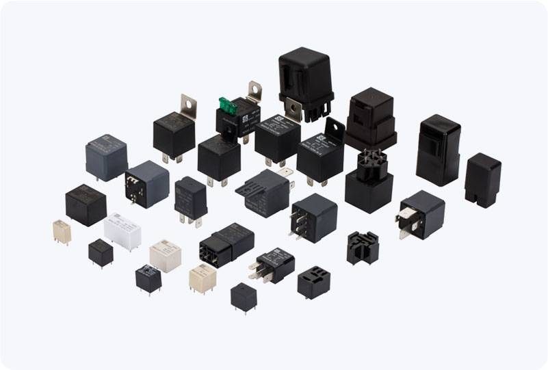
What is a PCB Electromagnetic Relay? A PCB electromagnetic relay is an electromechanical device that uses an electromagnetic coil to open or close a set of contacts, allowing electrical signals to be switched between different circuits. These relays are commonly found in applications that require electrical isolation between the control and the load circuits, which is often necessary for the safe operation of high-power systems. The PCB relay features an electromagnetic coil wound around a soft iron core, which, when energized, generates a magnetic field. This magnetic field causes a movable armature to shift, changing the position of the relay’s contacts. These contacts typically consist of one or more sets of Normally Open (NO) or Normally Closed (NC) contacts, allowing the relay to either complete or break the circuit depending on its configuration.